As Hardware Description Languages (HDL) do not support definitions of clock characteristics like the frequency and phase, this definition needs to be defined with timing constraints within Vivado. But why timing constraints / clock constraints must be defined in general?
It is because the designer must tell Vivado™ the frequency (and other parameters if necessary) of a clock which is used inside the FPGA and coming from an input pin. If a clock is connected to an input pin and the frequency of the clock is not specified, Vivado™ (the static timing analysis) will not calculate the timing at all. If a clock is specified, the timing for all the static timing paths which are running with this clock will be calculated.
There are more things which must be constrained in terms of timing, but for now, we will have a look at timing constraints for clocks.
Let us have a look at primary clock constraints. A primary clock constraint describes a timing constraint for a clock object where the syntax defines a clock period, a clock phase, and the waveform characteristic – not dependent on propagating dependencies. Typically, the user defines a primary clock constraint for all external clocks, taking their input pins into account.
This is a simple »primary clock« constraint:
create_clock -name
A name for the clock, the period in ns, and the port to which the clock is connected to (FPGA pin) has to be defined.
The option -waveform can also be added to define a specific pulse meander (default is a pulse width ratio of 50 % high and 50 % low).
In general, there are three possibilities to define the needed timing constraints like the one mentioned above:
-
1. Timing constraints can be entered directly into a constraint file (.xdc).
2. The Vivado tool »edit timing constraint« can be used. You can define your clock in the Vivado™ GUI.
3. The Timing Constraint Wizard can be used. In this case, the whole design will be analysed and the user is guided through different needed timing constraint also other than clock constraints. This is helpful for beginners and if it is not clear how to start and which timing constraints are needed in general.
For MPSoC or Versal™ devices, the clock for the programmable logic is mostly used from the processing system. In this case, the required clock constraint is auto created. This type of constraint is called »auto generated clock«. Additional clock constraints are not needed for this type of clocks. This is also the case for the Vivado™ IP »Clocking Wizard«. It can be used to configure PLLs and MMCMs and it is also creating a primary clock constraint for the clock which is used as an input to the PLL / MMCM.
Clocks which are defined and generated in the Clocking Wizard are also auto generated clocks. In the following picture a part of a design is shown, where primary clocks and auto generated are highlighted:
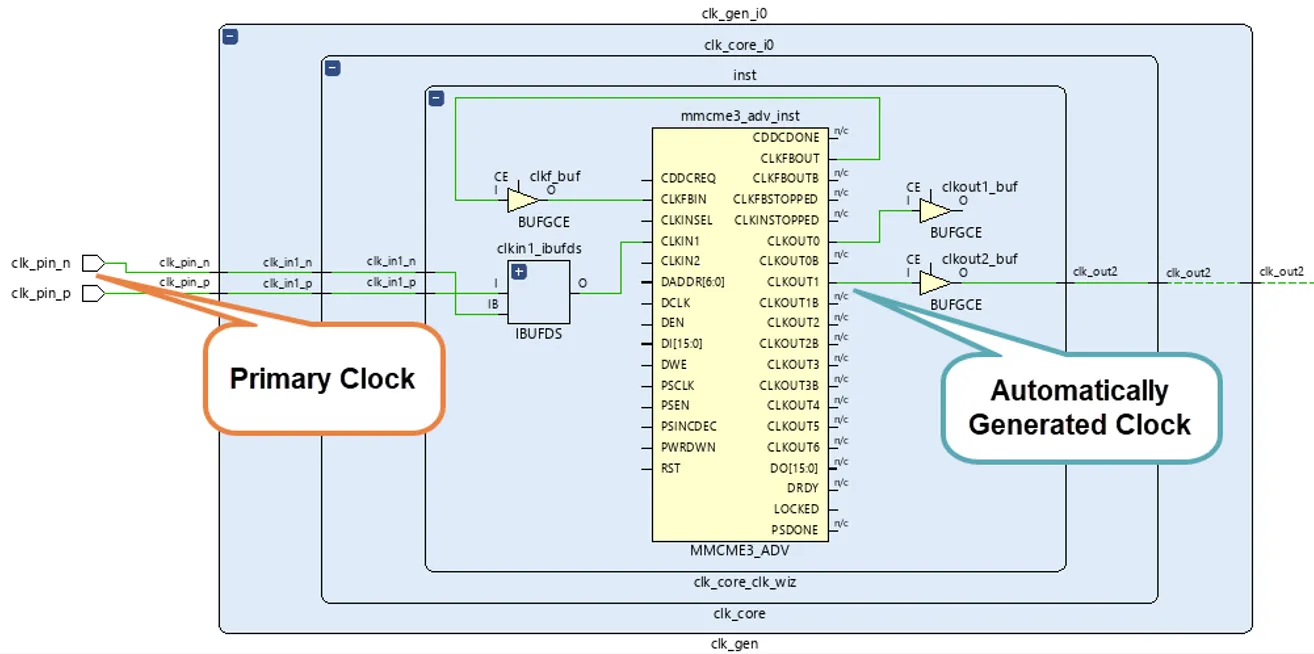
Example of a primary and an auto generated clock
The next type of clock constraints where we want to look at, are so called »generated clocks«.
If all clocks in the FPGA are distributed in a direct manner from the ports by only including clock buffers so that all clock pins have a same clock characteristic as the clocks from the input ports, primary clock constraints are sufficient without a need for generated clock constraints. But whenever a clock characteristic changes in the hardware architecture defined from IPs and user HDL files, a generated clock constraint specifies this clock.
Let us look at two typical examples where a generated clock constraint is needed.
a) A clock is created in the FPGA for an external device but not used in the FPGA fabric.
This is typically done with a counter and a toggle flip-flop. For the user, the output signal of the toggle flip-flop is a clock, because it was exactly designed so that the output is a toggling signal with a 50 / 50 duty cycle. For Vivado™ this is not a clock. It is a data signal. In this case the user must tell Vivado™ that this signal is clock and this is done by using a generated clock constraint.
b) When a clock division with counters is created and it is used as an enable for a clock (enable port of a clock buffer), a »generated clock« constraint must be defined.
The syntax of a generated clock constraint looks like that:
create_generated_clock –name
The key point is to tell the relationship regarding the source clock. The following picture shows an example of case b), where the enable signal of a BUFGCE is user controlled.
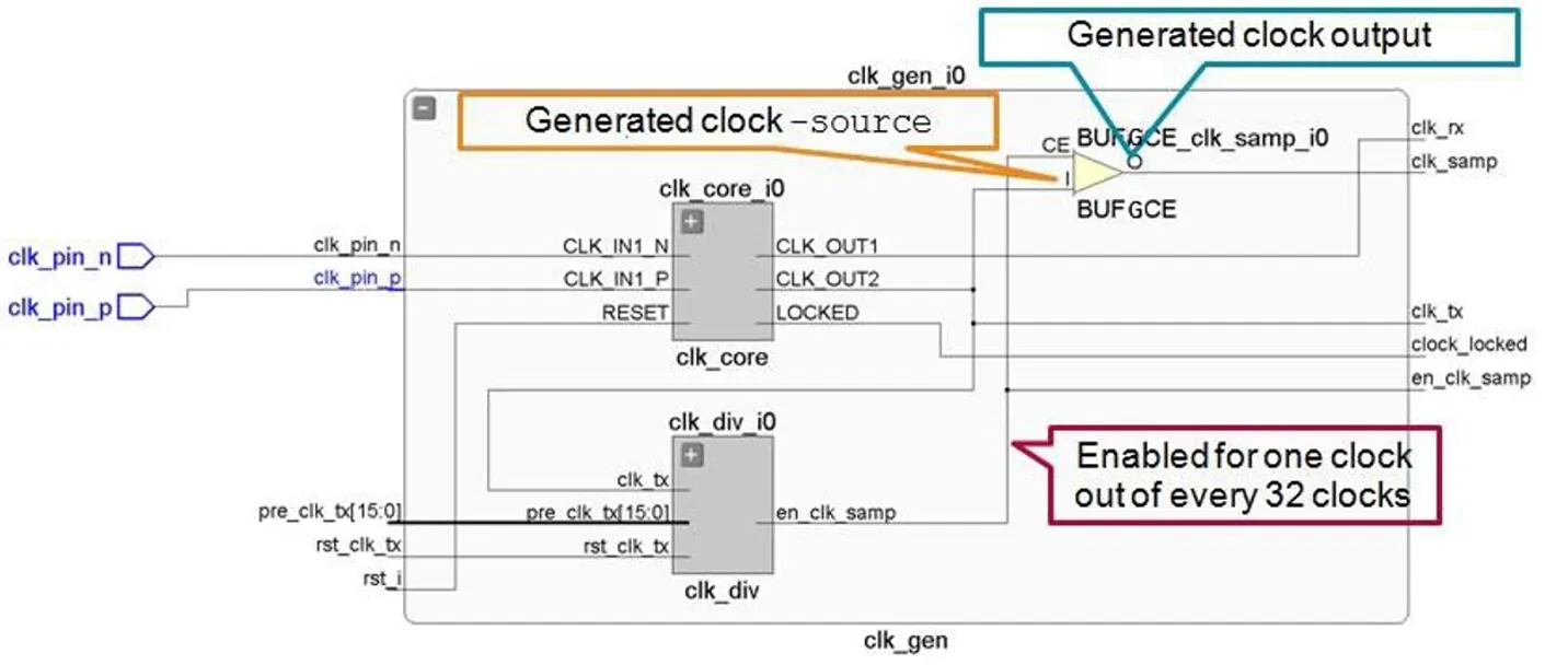
Example of a generated clock
To check if all clocks in the design are defined in terms of timing constraints, the command report_clocks can be executed.
This can be done by typing the command directly into the TCL console after synthesis or implementation (when a netlist is opened). The report can also be found in the Vivado™ GUI in the project navigator when a synthesized or implemented design is opened.
If you would like to deepen your Timing expertise, join our »Compact Timing Constraints and Analysis« training, and take your skills to the next level.